Description
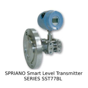
Spesifikasi SPRIANO Smart Differential Pressure Transmitter Series SST57B :
- Merk : SPRIANO
- Model : SST57B
Measuring range and span limits
| REF. | NOM. Range (mbar) | SPAN (mbar) min. max. | Range Limit (mbar) min. max. |
| B | 0/18 | 1,125/36 | -18/+18 |
| C | 0/50 | 3,125/100 | -50/+50 |
| D | 0/350 | 22/700 | -350/+350 |
| E | 0/1000 | 63/2000 | -1000/+1000 |
| F | 0/2500 | 156/5000 | -2500/+2500 |
| G | 0/5000 | 313/10000 | -5000/+5000 |
| H | 0/10000 | 625/20000 | -10000/+10000 |
Functional Data
With reference to the following, please note these definitions:
Nominal range : (referred to the sensor mounted in the instrument) the measured pressure range for which the sensor has been designed.
Defined as a minimum and maximum value.
Nominal span : the interval between the minimum and maximum values of the sensor nominal range. The span is a single number.
Measuring range : the minimum and maximum range values for whic the transmitter is to be calibrated.
Measuring span : the interval between minimum and maximum values of the measuring range.
Input scale initial value or zero input : minimum pressure value within in the measuring range.
Input full scale value : maximum pressure value within in the measuring range.
1) Transmitter Parameters.
The parameters that are available for display and setting are:
Measuring span : possibility to change from 6,25% to 100% of the nominal span.
Zero adjustment: digital calibration ± 15%.
Linearity adjustment : 8 points within the nominal range.
Low/upper range values : they can be set within the nominal range provided that the span greater than minimum span.
Damping : digitally adjustable from 0 to 15 sec. (minimum response time ~ 0,1 sec.).
Reverse output : automatically obtained via software.
Transfer function : linear/square root via software.
Self test : in case of malfunction the analog output is forced to the failsafe state of 3,8mA or 23,2mA.
Measuring units : 14 different pressure units or % of the measuring span, selectable via software.
2) Physical Characteristics.
Power supply : 12,5 – 30 Vdc with no load.
Output signal :
Analog 4-20mA, 2 wires.
Digital using HART®
Settling time : 120ms (at 27°C).
Nominal range 18-50 mbar :
Max static pressure : 50bar.
Overpressure limits : 50bar on either side.
Nominal range 350-10000 mbar :
Max static pressure : 100bar.
Overpressure limits : 100bar on either side.
Process chambers volume : 2 cm3 approx.
Displacement : 0,2 cm3 at span max.
Ambient Conditions
Temperature
Process fluid : -60 ÷ +85°C (with finned arm max 350°C)
Housing : -40 ÷ +85°C
Handling and storage : -40 ÷ +90°C
Relative Humidity : 0 a 100% R.H.
LCD display reading : -10 ÷ +70°C
Performances
Unless otherwise stated the performance specifications refer to ambient temperature = 20° C. and nominal span. Unless otherwise stated, all errors are shown as a percentage of nominal span.
Accuracy rating: guaranteed within the following limits:
Resolution : < 0,01%.
Accuracy : < 0,075% including non linearity, repeatability and hysteresis
errors.
Dead band : negligible.
Influence Of Operating Conditions
Thermal drift : It is referred to – 10 ÷ +65°C range.
Zero : ± 0,1%/10°K. Span: ± 0,1%/10° K at nominal range.
Static pressure effect
Nominal range 18-50 mbar :
Zero: ± 0,4% / 10bar. Span : 0,4% / 10bar.
Nominal range 350-10000 mbar :
Zero: ± 0,2% / 10bar. Span : 0,2% / 10bar.
Over range effect
Nominal range 18-50 mbar :
Zero : on either side ± 1% at 50bar.
Nominal range 350-10000mbar :
Zero : on either side ± 1% at 100bar.
Power supply effect :
Negligible between 12,5 and 30 Vdc.
Physical Specifications
Process wetted parts :
Diaphragm in AISI 316 L/Hastelloy C – process chambers, adapters, drain and vent plugs AISI 316 – gaskets PTFE + Viton + bolts carbon steel / AISI 304.
Housing : die cast aluminium alloy AL UNI 3571 finished with epoxy resin (RAL 5014).
Filling fluid : silicone oil.
Nameplate : stainless steel, fixed on housing.
Bracket for 2″ pipe mounting : zinc coated carbon steel.
Calibration
Standard : at nominal range, direct action.
Optional : at the conditions specified with the order.
Environmental protection : the transmitter is dust and sand tight and protected against sea waves effects as defined by IEC IP 66. Suitable for tropical climate operation as defined in DIN 50.015.
Process connections : ¼” NPT F on process chambers, ½” NPT F on the adapters.
Electrical connections : two entries on electronic housing, 1/2″ NPT and cable gland PG 13,5 for 7 to 12mm diameter cable.
Terminal board : 2 terminals for signal wiring up to 1,5 mm2 (14 AWG). Connection for ground and cable shield.
Mounting position : any position.
Options
Static pressure : 200bar.
Housing : AISI 316.
Equipment and Protection System ATEX 94/9/CE
Ex ia IIC T6 with Tamb -40 °C ÷ +60°C
Ex ia IIC T5 with Tamb -40 °C ÷ +75°C
Group II Class 1G suitable for Zone 0,1,2 – EN60079-10
Power supply parameters :
Ui = 30V, Li = 100mA; Pi = 0.75; Ci = 10 nF; Li = 0.2 mH.
Electromagnetic Compatibility
Conforms to the standard CEI EN 61326-1 in accordance with
89/336/EEC and following medications.